

Simi Valley, CA · July 2025 · Southern California Edison / City of Simi Valley
Turbines, stacks and a skylight. The array went around them.
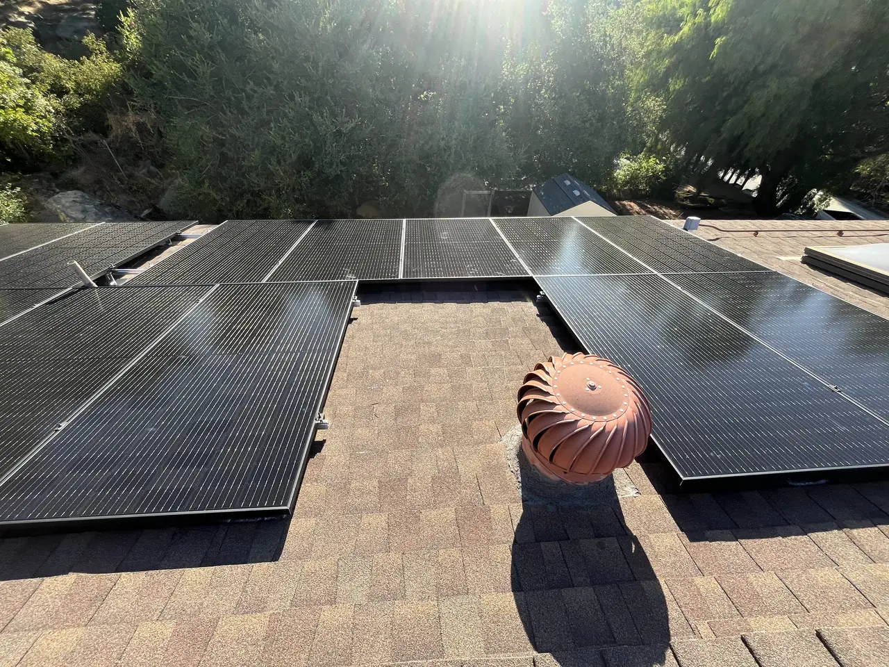
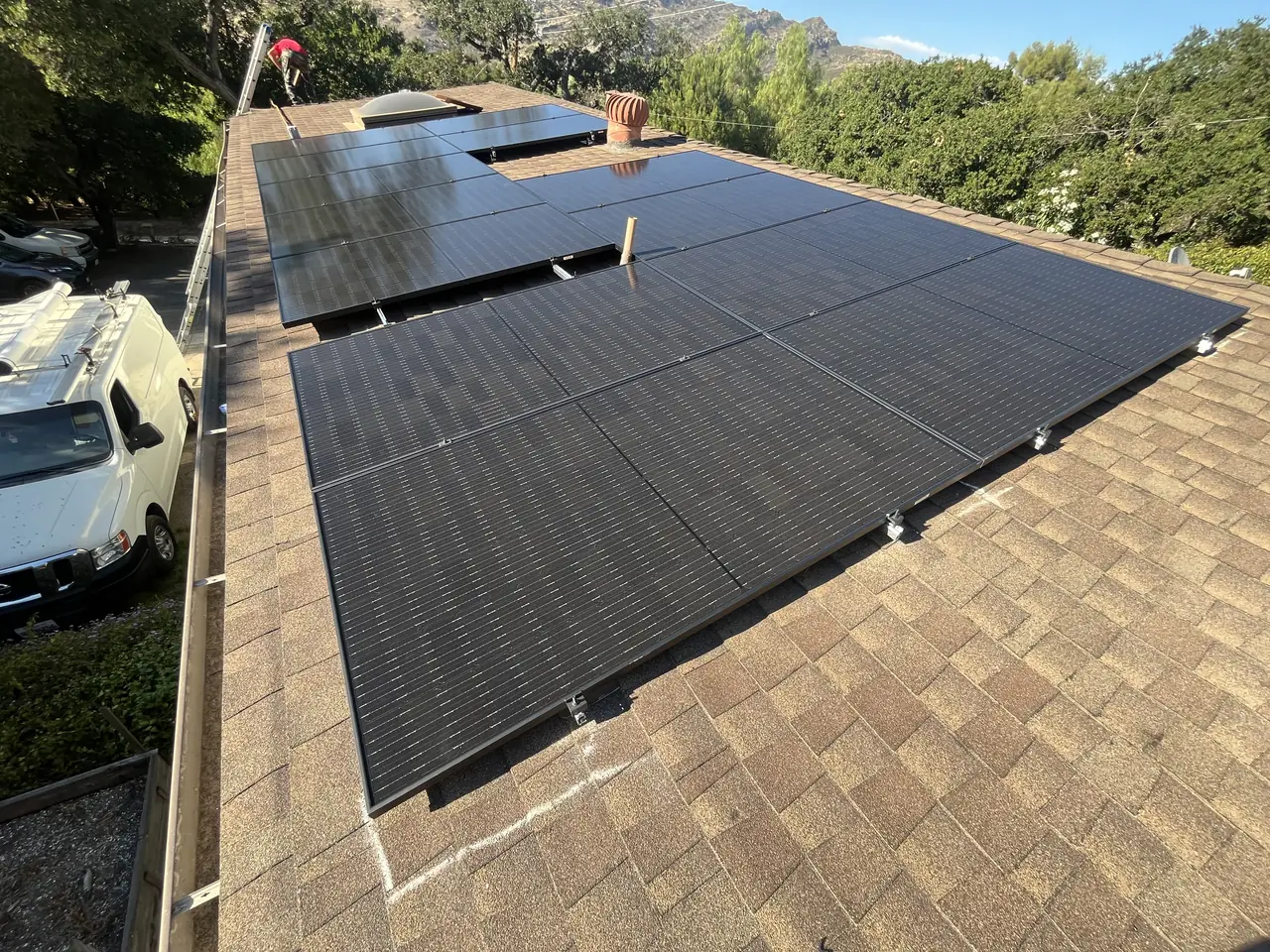
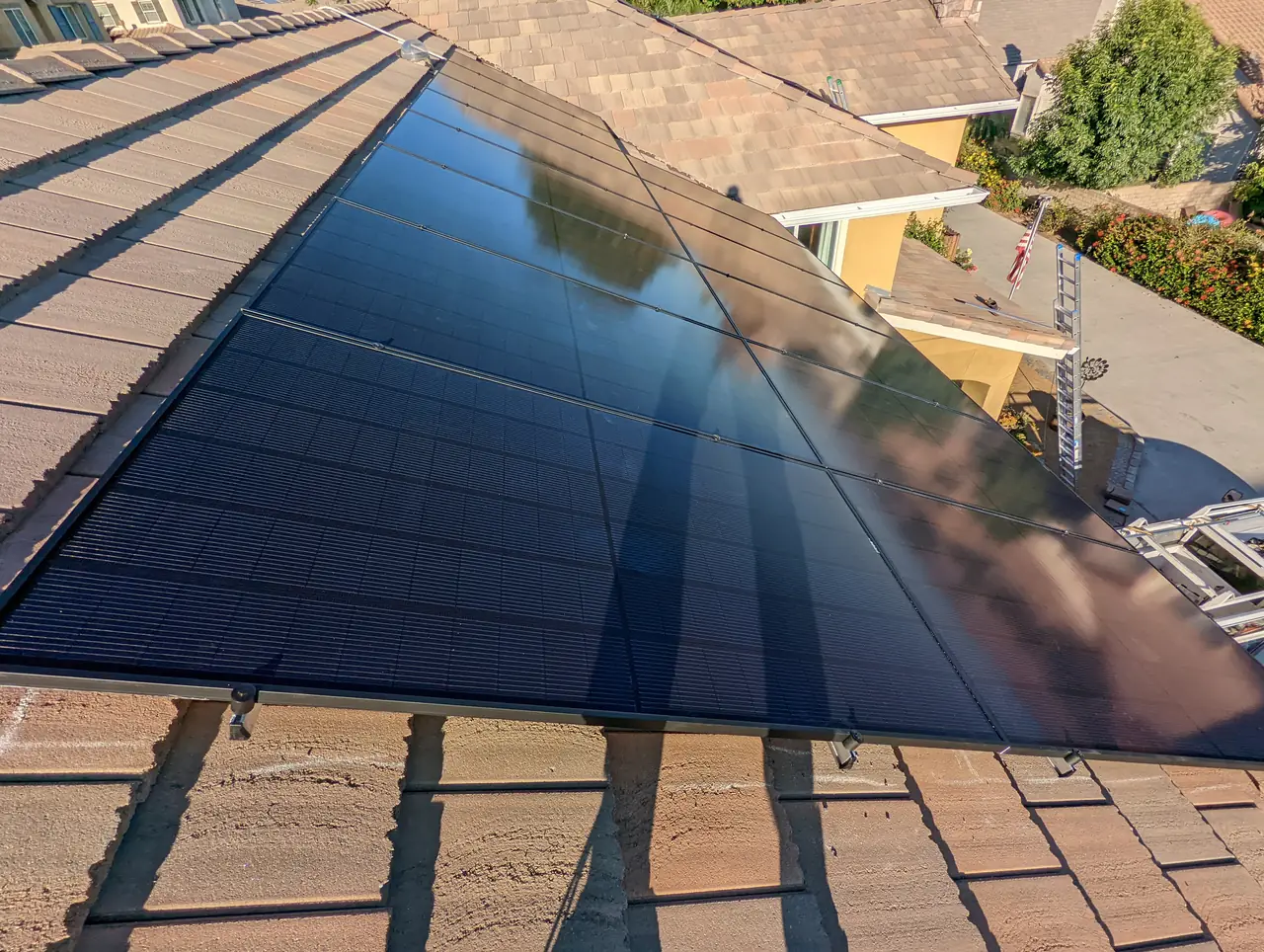
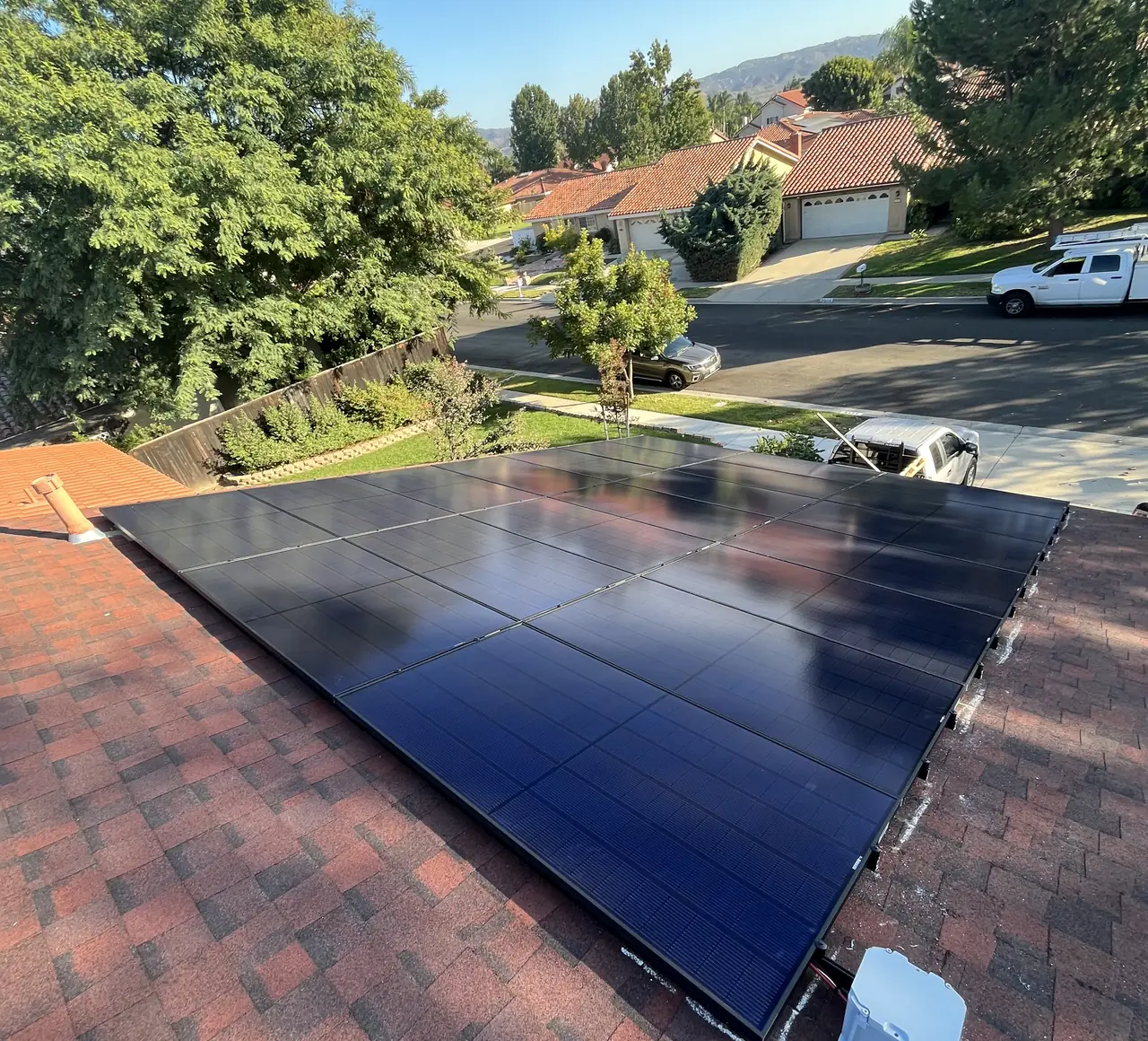
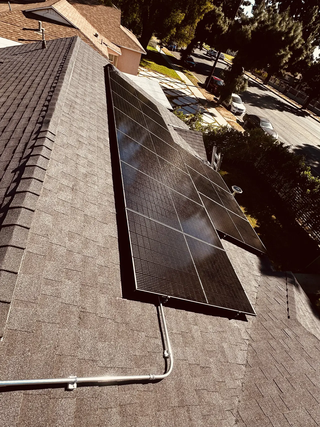
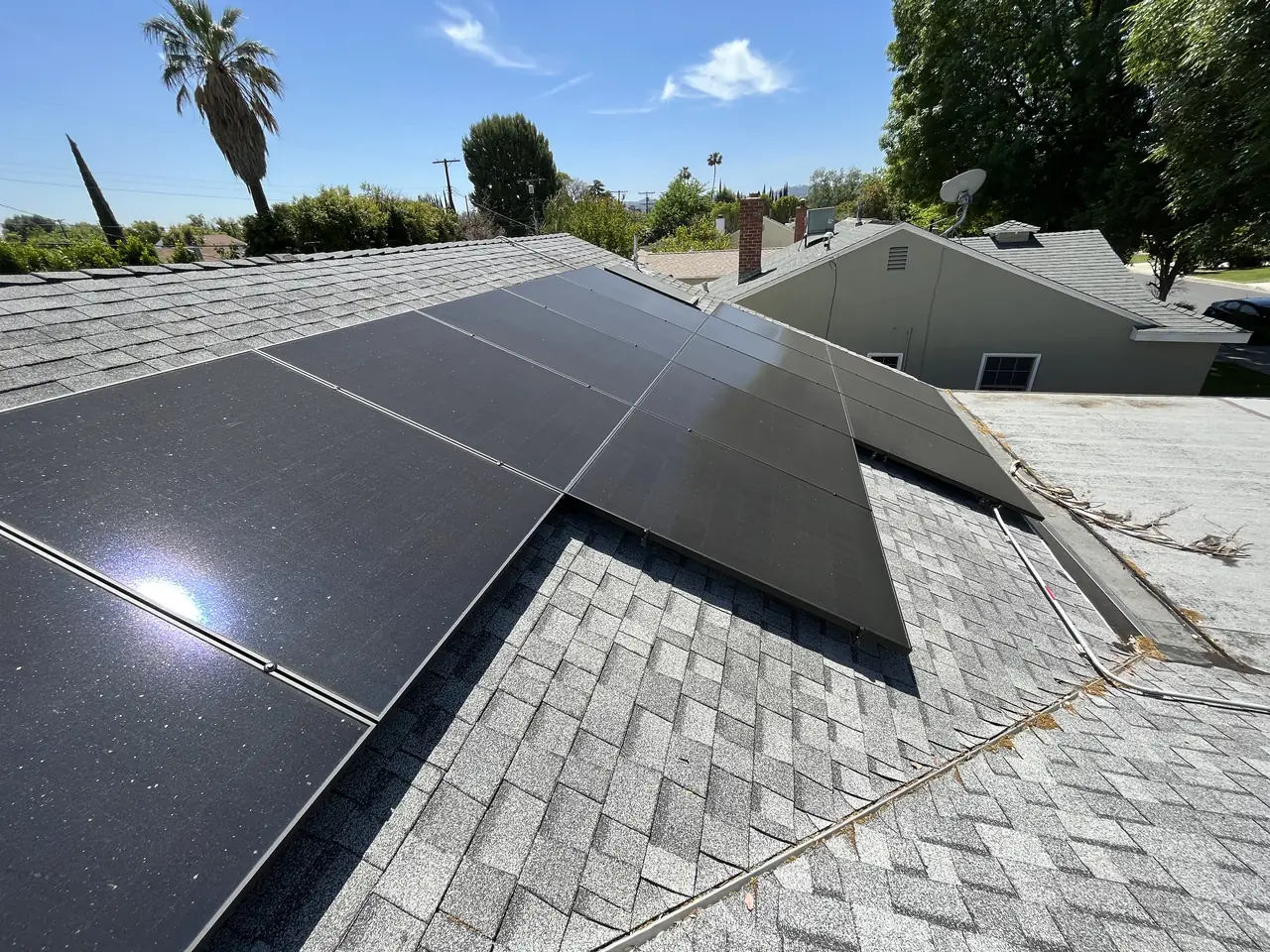
A multi-plane array on a Simi Valley shingle roof that was already carrying attic turbines and vent penetrations. The layout is what the roof allowed, not what the software drew.
Roof hardware is not decoration and most of it cannot simply be moved. Turbine vents ventilate the attic and their positions are set by the ventilation calculation for the house. Plumbing stacks come up where the drainage is. Flues have clearance requirements around them. So the array is drawn as several rectangles that fit between all of it, with the rails cut into short spans and the groups wired back to one system. It costs layout efficiency and it is the correct answer. On older Simi Valley roofs it is the usual answer rather than the awkward one.
At a glance
- Roof
- Composition shingle, several planes
- Existing hardware
- Turbine attic vents, plumbing stacks, a skylight
- Array layout
- Multiple groups laid out around the existing penetrations
- Racking
- Rails run in short spans between obstructions
- Attachments
- Individually flashed
- Pitch
- Measured on the roof with an angle finder
- Storage
- Wall-mounted battery on an exterior wall
- Utility / AHJ
- Southern California Edison / City of Simi Valley
The story
The first thing a Cali Energy crew does on a roof like this is count what is already there. Turbine vents, the spinning kind that sit along the ridge on older older houses here. Plumbing stacks coming through at whatever spacing the drainage happens to use. A skylight. Each of those is a fixed point the array has to accept.
People assume that hardware can be moved, and occasionally some of it can, at a cost and with its own permit. Mostly it cannot. Turbine vents are part of the attic ventilation for the house and their number and placement come out of a calculation, not a preference; removing two of them to make room for four more modules trades a documented ventilation requirement for a little production. Plumbing stacks come up where the pipes are. Flues carry clearance requirements that are about fire, not tidiness.
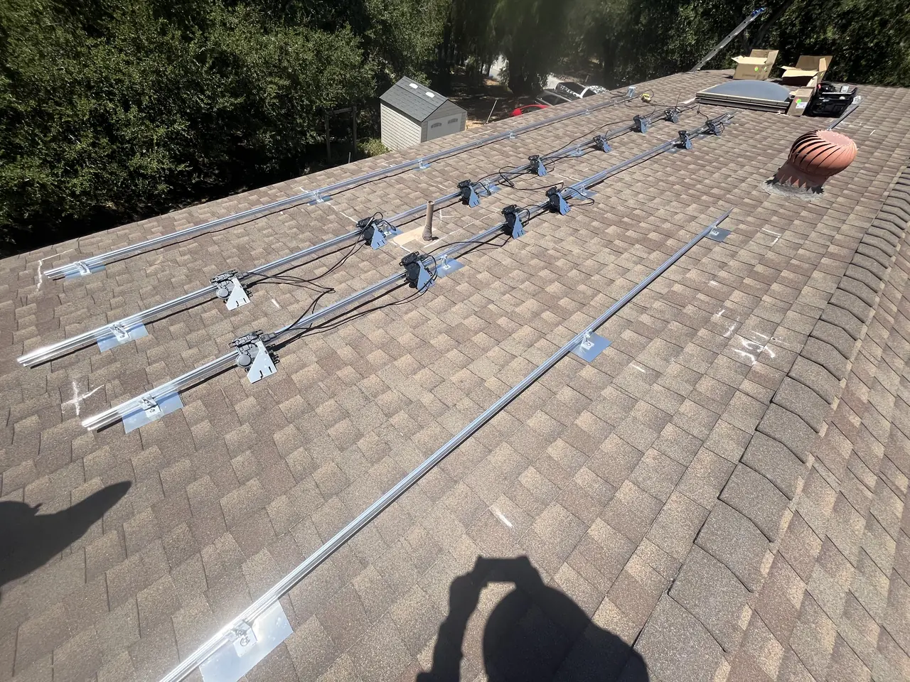
So the layout on this house is not one clean rectangle. It is several groups, each sized to the space between whatever is fixed, on more than one plane. The rails run in short spans rather than long continuous runs, which means more attachments, more end clamps and more flashed penetrations than a simple roof would need.
Two things make that affordable rather than painful. The first is module-level electronics: with a microinverter or optimizer under each module, groups on different planes and orientations do not drag on each other, so the array can be broken up wherever the roof demands without a production penalty. The second is doing the survey properly. Pitch measured on the roof with an angle finder, obstructions mapped in place rather than read off an aerial image, and the layout built from that.
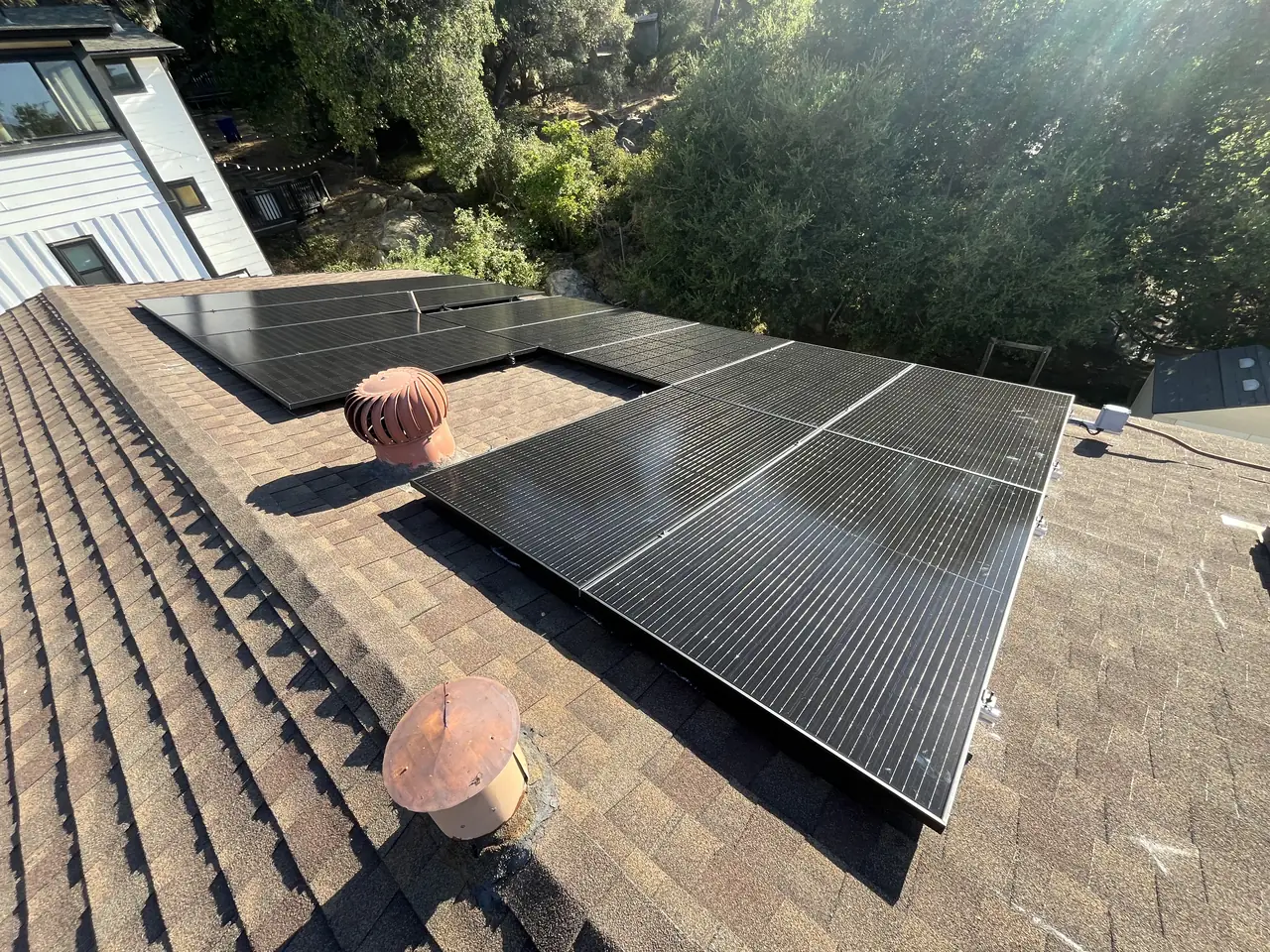
The gaps that result look like wasted roof from the street and they are not. Some of them are clearance around a vent. Some are the fire pathway the code requires. Some are simply the width left between two fixed objects, which happened to be less than a module. A layout with no gaps on a roof like this one would mean something had been ignored.
The electrical side came down to an exterior wall, where the inverter, the disconnects and a wall-mounted battery sit together. On a house where the array is broken into groups, that wall is where it becomes a single system again.
How it ran
| Before the day | Roof surveyed; pitch measured and obstructions mapped in place |
|---|---|
| Before the day | Array laid out as groups between the existing roof hardware |
| 16 July 2025, morning | Attachments located, lagged and flashed |
| 16 July 2025, midday | Rails set in short spans between obstructions |
| 16 July 2025, afternoon | Modules laid and connected group by group |
| 16 July 2025, close of day | Equipment wall completed and the roof left clear |
An installation-day record. This timeline reflects this property and this roof.
What we did
- Surveyed the roof in place and mapped every existing penetration before drawing a layout (C-10).
- Measured the pitch on the roof rather than taking it from imagery.
- Laid the array out as separate groups that respect ventilation hardware and clearances.
- Set rails in short spans between obstructions, with every attachment flashed individually.
- Kept the attic ventilation intact rather than removing vents to gain module positions.
- Brought all groups back to a single equipment wall with the inverter, disconnects and battery.
System specifications
| Roof | Composition shingle, several planes |
|---|---|
| Obstructions worked around | Turbine attic vents, plumbing stacks, skylight |
| Array layout | Multiple groups rather than a single block |
| Racking | Short rail spans between fixed points |
| Attachments | Individually flashed under the course above |
| Electronics | Module level, so split groups carry no production penalty |
| Balance of system | Inverter, disconnects and wall-mounted battery on one wall |
| Utility / AHJ | Southern California Edison / City of Simi Valley |
Is your project like this one?
- Your roof has turbine vents, stacks or skylights in the middle of the good area.
- A layout you have been shown covers the whole roof and you are wondering what happened to the vents.
- Somebody has offered to relocate your roof vents to fit more modules.
- Your array will be split into groups and you want to know what that costs.
Cali Energy in Simi Valley
Simi Valley is a city in Ventura County: permits run through the City of Simi Valley Building & Safety Division, interconnection through Southern California Edison.
Older Simi Valley houses carry a lot of hardware on the roof: turbine vents for attic ventilation, plumbing stacks, flues and skylights. An array has to be designed around that, and what looks like wasted space is usually a rule.
This installation is on the Simi Valley projects page alongside the others, and what the work covers is set out on the Simi Valley service area page.
- License and classifications: CSLB #1032379
- Official reference for this process: California Building Standards Commission — California Building Standards Code
- Official reference for this process: California Energy Commission — solar equipment lists
Frequently asked questions
Can roof vents be moved to fit more solar?
Sometimes, rarely for free, and often not at all. Turbine and static vents are part of the attic ventilation required for the house, calculated from attic area, so removing them trades a documented requirement for a few modules. Plumbing stacks come up where the drainage runs. Relocating any of it is separate work with its own permit and its own roof penetrations.
Does Cali Energy survey the roof before designing in Simi Valley?
Yes, on site rather than from imagery. Cali Energy measures the pitch with an angle finder and maps every vent, stack, flue and skylight in place, then builds the layout from that. An aerial image misses hardware and gets the pitch close rather than right. Fifteen completed Simi Valley projects are on our projects page. Our license is CSLB #1032379.
Why does my layout have gaps in it?
Because something is there. Clearance around a vent, the fire access pathway the code requires, or simply a space between two fixed objects narrower than a module. On a roof carrying a lot of hardware a layout with no gaps is a sign that something has been ignored rather than a sign of good design.
Does splitting an array into groups reduce output?
Not with module-level electronics. A microinverter or optimizer under each module means groups on different planes work independently, so the array can follow the roof. What the split does cost is installation: more rail ends, more attachments and more flashed penetrations than a single clean rectangle would need.
What this would look like on your roof
Planning solar in Simi Valley? Tell us your utility, your roof and what your bill looks like now, and we will model what a system like this would do on your house before you commit to anything.
Or call +1 (323) 844-7777 · Cali Energy, Northridge · CSLB #1032379 (B, C-10, C-39) — design, permits, install and electrical under one licensed contractor.
Related
This timeline reflects this property and this permitting path. Updated September 2026.